Converting a KO vantage Esprit II stick transmitter to 2.4 Ghz using the FrSky "hack" module.

Why convert?

The Spektrum 2.4 ghz system is by far the most popular amongst racers in the UK.
However, for those of us that choose a stick transmitter, the choice is limited, and the KO module upgrade is now becoming scarce, as well as expensive.
Recently, I became aware of a number of extremely low cost 2.4 ghz transmitters based around chinese chipsets.
I tried one, but found it to be functional, but very poor quality. understandably at the price.
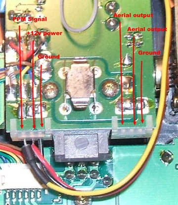
There are also a number of "hack" modules. Small self contained RF modules which need to be fed a voltage, and a PPM signal from the transmitter.
These link into the transmitter electrics after all of the signal processing has taken place, so preserve, model memories, end points adjustments, and all of the other cool computerised stuff your transmitter can do.
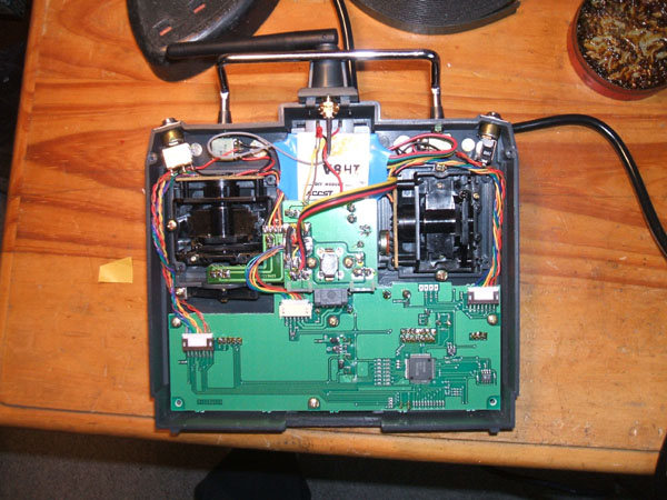
The best transmitters to upgrade are those which already have a RF module design, either externally with a removable module, or internally, where the RF circuit board is seperate and recognisable. In these cases, it is relatively easy to identify the PPM signal output required to feed to the hack module.
With other, (cheaper), transmitters, such the enry level 27mhz AM kits, it can be far harder to find the required PPM signal output. An effort which will normally require an oscilloscope. Of all the hack modules available, I finally came down to two choices, both around the £10 price with receivers being about the same.
i.e. A complete upgrade to 2.4 Ghz for circa £20 (TWENTY) UK Pounds.
  • Corona 2.4Ghz DIY Module Only (DSSS) CT8Z
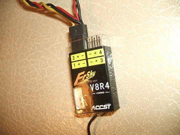
  • Frsky 2.4Ghz Conversion ( Hack ) Module V8HT
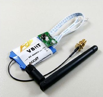
Fitting it into a KO stick transmitter

ko-aerial-board

The Antennae

I already have a hole in the top of the transmitter where the telescoping 40mhz aerial went.
Of course, the 2.4 Ghz antennae won't just fit in.
The aerial mount can be removed from the transmitter by undoing two locating screws.
From the inside, you can now carefully un a 10mm drill through, to widen the hole. This should provide just enough clearance to push the FrSky antennae through the hole far enough that it can fold down.
At this point, it should be an interference fit, (very tight), in the hole, and require no glue to hold it in place. If it is a bit loose, then using something like PTFE Plumbers tape will ensure that the antenae is replaceable when you break it. (Whereas gluing with hot glue or epoxy is a non reversible process.)

The LED

daughter board

The bind button

To get to the bind plug, I needed to drill a hole through from the front to allow a paper clip or similar to be inserted to operate the bind button.
Measuring the distance between the LED and the Bind button put the location of the hole as straight through the N in "Racing"
I started the hole with a lexan hole reamer, then drilled through with a 2mm drill.
Now the LED is just a push fit, so if you get too vigorous pushing on the bind button with your paper clip, you'll push the daughterboard away from the locating hole.
I considered glueing it in, but in the spirit of reversibility, I came up with another solution.
Note the two screws holding the trim ratchets in place. By carefully removing these screws, one at a time, it should be possible to fix something in place to hold the back of the daughter board steady.
I used a piece of lexan, with a pencil eraser glued to it with double sided tape.
The rubber eraser should be 6mm high, when stuck to the lexan.

bind-hole

The module

module-in-place

Finishing off

Now all that's left is to solder the wires to the pads, rather than just poke them into the socket.
This provides a better connection, and also allows the KO module case to be reinserted into the bottom of the transmitter to keep it looking profesional and tidy.
Remember to remove the circuit board from the plastic KO module case before reinserting, because even without a crystal or aerial, it may transmit interference on the 40Mhz band. Also, if left in, it will consume electricity, and reduce the amount of time your transmitter will run.
Here is a picture of the completed job, just before screwing the back on, the module in place, with the wires just gently bent out of the way. note that I have left the original LED in place. You may want to clip it off, or insulate the wires and tape it down to stop it moving about inside the case.

Receiver connections

receiver pinouts

Binding

Binding follows the same format as most other 2.4ghz systems.
  1. Turn the transmitter on while holding down the bind button.
  2. Ensure the red LED on the transmitter is flashing.
  3. Power up the receiver while holding the bind button.
  4. The Receiver LED flashes to indicate bind is successful.
  5. Turn of Receiver.
  6. Turn off Transmitter.
  7. Switch on and use as normal.